Data Logger
Here's the challenge.
The Nuvinci literature quotes the power consumption or their shifter to be between 4W and 35W so for my 12v system
that's anything from 0.32A to 2.8A. I had no idea what the energy requirement would be for a typical ride. Early trials
indicated at least 3 hours use on a 3.2Ah 12v battery. So I took two of them on the IoW Randonnee to be sure of making it round.
In fact I was 7 hours in that saddle with a battery stop after 4 hours, which considering how much shifting it was doing,
1100m of climb and descent, I was quite pleased with that result.
I was advised that the data logger would be an easy project. Amazingly it was. It involved the purchase of an
Arduino Uno
and an
SD shield, a few resistors and capacitors for the
voltage divider and a
current sensing module off eBay,
a box to house it in and a short piece of code which I plagiarized and tweaked from the many bits of Arduino code available on the web. Notably this from
Ladyada's Temp and Light
Logger or in
pdf format.
Another great Arduino Temp logger blog can be found at
Lallafa's Blog.
For some background on the Arduino board here's a great YouTube clip from Fritzing and you can download their Fritzing Software for circuit design, including the Arduino board.
Component suppliers were:
- Arduino Uno from ProtoPic or Amazon
- SD shield from ProtoPic
- Electrical components from Technobots
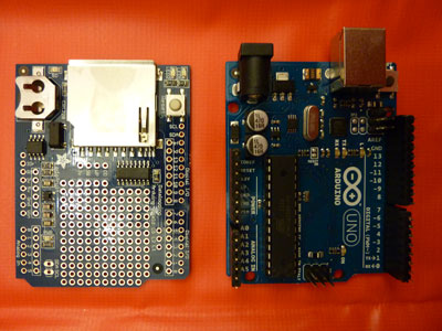
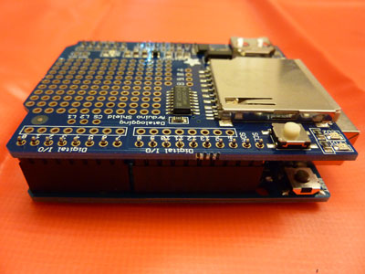
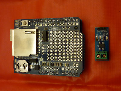
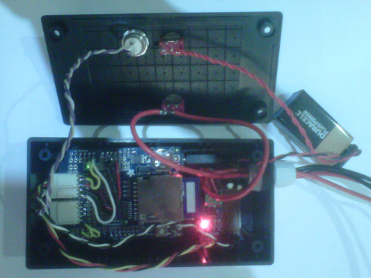
So here are a few pictures showing the main boards and how it all goes together. The SD shield sits on top of the Uno with the header pins soldered as assembled to ensure alignment. The small board on the right is the
ACS712
current sensing module (5A range). this will sit on a small vero board also containing the voltage divider circuit which drops the 14v battery voltage down to within the 0-5v analogue pin input limit of the Arduino.
A quick dry run to check everything fits in the box and the green light still comes on....
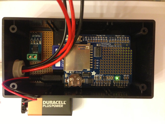
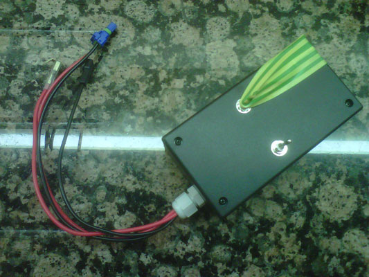
Here's the final assembly prior to the first on bike logging adventure. All that remains is to add some foam to keep everything in place.
And with the lid on, waiting for some stickers.
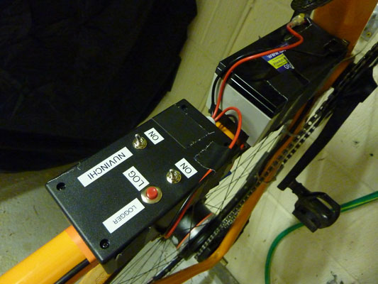
The switch on the right is the main power switch for the Nuvinci shifter. the switch on the left is to power up the logger and hidden under the tape is a button to initiate logging.
Here it is installed on the bike.
As always having something working on the bench doesn't always mean things will work in the field... Having said that it did log the required data, the current levels all looked sensible but the battery voltage climbed with time. Clearly I haven't found a way to solve the earths energy crisis so there had to be another explanation. After all haw can a circuit with three components, two resistors and a capacitor fail to deliver. some delving on the Arduino forums yielded the answer; drifting 5v reference voltage. It doesn't affect the current sensor as it's 5v supply is the reference voltage and so it's ratiometric but not so for the voltage divider which only shares a common ground. Second point, check the Arduino supply voltage, those PP9's don't last forever. Fit a new one and the reference voltage is a nice stable 5v, but it won't last so a better solution is required. The boards 3.3v supply is better regulated so I now log this and correct the reference voltage with it. Now the battery voltage drops as the battery discharges, happy days.
It took a while to locate a concise guide to writing Arduino code as most books also include in depth hardware explanations as well. The Arduino Programming Notebook is a perfect code summary. I wish guides like this were available for the code libraries people write.
Here's my code.
/*
powerlogger code
created 30 April 2013 by MRW
ver 1.0
code flow and algorithms plagiarised from Arduino example sketches www.arduino.cc
*/

// libraries required

#include ‹SD.h›

#include "RTClib.h"

#include ‹Wire.h›

#define LOG_INTERVAL 100 // define logging rate at 10Hz

/* decide how many milliseconds before writing the logged data permanently to disk
   set it to the LOG_INTERVAL to write each time to loose no data on power off
   set it to 10*LOG_INTERVAL to write all data every 10 data reads, you could lose up to
   the last 10 reads if power is lost but it uses less power and is much faster
*/

#define SYNC_INTERVAL 10000          // mills between calls to flush() - to write data to the card 10s or 100 samples

uint32_t syncTime = 0;              // time of last sync()

#define ECHO_TO_SERIAL 0            // set true (1) for debugging to monitor
#define WAIT_TO_START  1            // Wait for button push to start logging

// define the digital pins for the LEDs

#define greenLEDpin 3               // green led on D3
#define redLEDpin 4                 // red led on D4

// define the Analogue inputs

#define vBattpin 0                  // analog 0 reads output of voltage divider
#define iBattpin 1                  // analog 1 reads output of current sensor
#define vRef33 2                    // analog 2 reads the 3.3v reference voltage

// define constants

const int chipSelect = 10;          // CS pin required by SD library
const int pushButtonpin = 2;        // push button attached to D2

RTC_DS1307 RTC;                     // define the real time clock object.

// the logging file

File logfile;

// Error handling subroutine

void error(char *str)
{
 // print error to serial
 Serial.print("error: ");
 Serial.println(str);
 // turn on the red led to signify an error
 digitalWrite(redLEDpin, HIGH);
 while(1);                          // stop here indefinitely
}

void setup()
{
  Serial.begin(9600);
  Serial.println();

// set debugging LEDs as outputs

  pinMode(redLEDpin, OUTPUT);
  pinMode(greenLEDpin, OUTPUT);

// set the input pins

  pinMode(pushButtonpin, INPUT);    // D2
  pinMode(vBattpin, INPUT);         // A0
  pinMode(iBattpin, INPUT);         // A1
  pinMode(vRef33, INPUT);           // A2

//illuminate the red & green LEDs to show we are waiting for the button to start the logging

  digitalWrite(redLEDpin, HIGH);
  digitalWrite(greenLEDpin, HIGH);

#if WAIT_TO_START
#if ECHO_TO_SERIAL
  Serial.println("press button to start");         // Press the button to start
#endif
  while(digitalRead(pushButtonpin) == LOW);        // While button low wait here
#endif

//Button pushed so LEDs off

  digitalWrite(redLEDpin, LOW);
  digitalWrite(greenLEDpin, LOW);

#if ECHO_TO_SERIAL
Serial.print("Initializing SD card...");
#endif

  pinMode(10, OUTPUT);            // make sure that the default chip select pin is set to output even if not used


  if (!SD.begin(chipSelect))      // see if the card is present and can be initialized:
  {
    error("Card failed, or not present");
  }

  #if ECHO_TO_SERIAL
  Serial.println("card initialized.");
  #endif

  char filename[] = "LOGGER00.CSV";            // create a new file
  for (uint8_t i = 0; i < 100; i++)
  {
    filename[6] = i/10 + '0';
    filename[7] = i%10 + '0';
    if (! SD.exists(filename))
    {
      logfile = SD.open(filename, FILE_WRITE); // only open a new file if it doesn't exist
      break;  // leave the loop
    }
  }

  if (! logfile)
  {
    error("couldnt create file");
  }

#if ECHO_TO_SERIAL
  Serial.print("Logging to: ");
  Serial.println(filename);
#endif

  // connect to RTC
  Wire.begin();
  if (!RTC.begin())
  {
    logfile.println("RTC failed");
#if ECHO_TO_SERIAL
    Serial.println("RTC failed");
#endif
  }

  // Print logfile header to SD

  logfile.println("millis,date,time,vBatt,vBattRef33,iBatt");  // vBattRef33 is the vBatt corrected to a true 5v from the 3.3v ref voltage

#if ECHO_TO_SERIAL
  Serial.println("millis,date,time,vRef5,vBatt,vBattRef33,iBatt");
#endif

}

// Start of main program loop

void loop(void)
{
  DateTime now;

  delay((LOG_INTERVAL -1) - (millis() % LOG_INTERVAL));  // delay for the amount of time we want between readings

  digitalWrite(greenLEDpin, HIGH);                      // confirm sensor read with greed LED

// log milliseconds since starting

  uint32_t m = millis();              // Set m to on time
  logfile.print(m);                   // milliseconds since start
  logfile.print(", ");

#if ECHO_TO_SERIAL
  Serial.print(m);                    // milliseconds since start
  Serial.print(", ");
#endif

  now = RTC.now();                   // fetch the time

  logfile.print(now.year(), DEC);
  logfile.print("/");
  logfile.print(now.month(), DEC);
  logfile.print("/");
  logfile.print(now.day(), DEC);
  logfile.print(",");
  logfile.print(now.hour(), DEC);
  logfile.print(":");
  logfile.print(now.minute(), DEC);
  logfile.print(":");
  logfile.print(now.second(), DEC);

#if ECHO_TO_SERIAL
  Serial.print(now.year(), DEC);
  Serial.print("/");
  Serial.print(now.month(), DEC);
  Serial.print("/");
  Serial.print(now.day(), DEC);
  Serial.print(",");
  Serial.print(now.hour(), DEC);
  Serial.print(":");
  Serial.print(now.minute(), DEC);
  Serial.print(":");
  Serial.print(now.second(), DEC);
#endif

// Read the 3.3v regulated voltage which is referenced to the 5v supply line
// Any drift in this signal reflects the drift in the 5v supply used as ref for the ADC

  int voltageReading33 = analogRead(vRef33);      // This is the value of the 3.3v line when referenced to the 5v on board supply
  float vRef5 = 3376.0 / voltageReading33;        // Obtain the floating value of the 5v reference (remember to use dec pt in float

// The voltage divider uses 6.8k & 3.3k resistors

  int voltageReading = analogRead(vBattpin);      // Read the signal from the voltage divider
  float vBatt = voltageReading * 0.0149589;       // (5v/1023 bits)*(10.1ohm/3.3ohm)

  // vBattpin33 is referenced to a corrected 5v using the 3.3v supply on the board which is regulated

  float vBattRef33 = voltageReading * vRef5 * 0.003; // corrected voltage (vRef5/1023bits/(10.1ohm/3.3ohm)

// iBattpin is referenced to 5v but doesnt need correcting as the sensor is ratio metric
// iBattpin gain is 0.185 v/A
// (iBattpin/1024 = Vin/5) & (Vin = Vcc/2 + 0.185 * I) therefore

  float iBatt = (analogRead(iBattpin) - 512) / 37.88;

// write data to SD card

  logfile.print(", ");
  logfile.print(vBatt);
  logfile.print(", ");
  logfile.print(vBattRef33);
  logfile.print(",");
  logfile.print(iBatt);
  logfile.println();

#if ECHO_TO_SERIAL
  Serial.print(", ");
  Serial.print(vRef5);
  Serial.print(", ");
  Serial.print(vBatt);
  Serial.print(", ");
  Serial.print(vBattRef33);
  Serial.print(", ");
  Serial.print(iBatt);
  Serial.println();
#endif

  digitalWrite(greenLEDpin, LOW);        // signify end of logging sample

  /*
   Now we write data to disk.
   Don't sync too often - requires 2048 bytes of I/O to SD card
   which uses a bunch of power and takes time
  */

  if ((millis() - syncTime) < SYNC_INTERVAL) return;
  syncTime = millis();

// blink LED to show we are syncing data to the card & updating FAT
  digitalWrite(redLEDpin, HIGH);
  logfile.flush();
  digitalWrite(redLEDpin, LOW);
}
Here's a sample of the logged data combined with some GPSLoggerII data for the ride.
The top trace (blue) is elevation.
The second trace (green) is speed, by GPS.
The third trace is the power consumption of the Nuvinci eHarmony.
The fourth trace (gold) is the current drawn.
The third (light green) and fourth (dark green) is the battery voltage where '33' refers to the voltage corrected by the regulated 3.3v board supply.
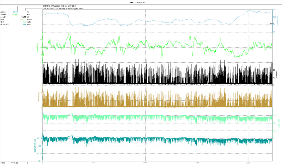
The figures listed top left are a mean of the entire log and shows power consumed as 3.8W.
Now on to the bike build
Following the completion of this first logger I've now build a second unit with a real time display.