Data Logger 2
 When my order for a $5 cadence display unit was cancelled by the supplier I decided to make my own.
After my surprising success with the first
data logger
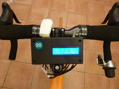
I felt confident to attempt something more adventurous with a real time display using an LCD 1602 (HD44780 with 16 digits in two rows).
Here it is temporarily fitted to the bike with tape.
For those who haven't read
data logger
here's some background on the Arduino board and a great YouTube clip from
Fritzing.
You can download their
Fritzing Software
for circuit design including the Arduino board.
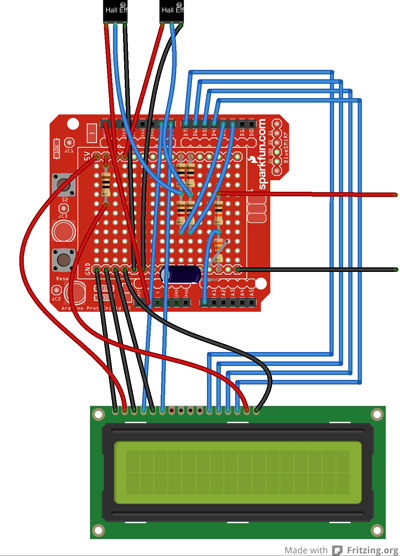 Here's my attempt at a pictorial representation of the Logger and Display using Fritzing.
It took a while to locate a concise guide to writing Arduino code as most books also include in depth hardware explanations as well.
The
Arduino Programming Notebook
is a perfect code summary.
Component suppliers were:
- Arduino Uno from Phenoptix or ProtoPic or Amazon
- SD shield from Phenoptix or ProtoPic
- Electrical components from Technobots
Here's my code.
/*
This sketch is to log and display parameters to SD card and an LCD 1602
The display is HD44780 compatible and uses the LiquidCrystal.h library
the LCD is run in 'Nibble' mode using D4,D5,D6,D7 & D4 for Enable and D9 for RS
Cadence/Speed is measured using a Cherry MP101401 Hall effect sensor on an interrupt line
Tilt and Compass heading are comms through  Ic2 (two wire)
The SD card is Adafruit and comms through SPI
D0 (Rx)
D1 (Tx)
D2 Cadence (interrupt)
D3 Speed (interrupt)
D4 Data7 = LCD14
D5 Data6 = LCD13
D6 Data5 = LCD12
D7 Data4 = LCD11
D8 Enable = LCD6
D9 RS = LCD4
D10 CS - SD Card SPI
D11 MOSI - SD Card SPI
D12 MISO - SD Card SPI
D13 SCK - SD Card SPI
A0 Battery voltage (5v ref)
A1
A2
A3
A4 SDA - Inclination & Heading
A5 SCL - Inclination & Heading
Full house on digital i/o
three spare analogue lines

V1.03
02/07/2013
*/

#include ‹LiquidCrystal.h›
#include ‹SPI.h›
#include ‹SD.h›
#include "RTClib.h"
#include ‹Wire.h›

// initialize the library with the numbers of the lcd interface pins
LiquidCrystal lcd(9, 8, 7, 6, 5, 4);

#define LOG_INTERVAL 100 // define logging rate at 10Hz
#define SYNC_INTERVAL 1000 // mills between calls to flush() - to write data to the card 1Hz
uint32_t syncTime = 0; // time of last sync()
#define numReadings 10 //number of readings to average vBatt over

// define the Analogue inputs; Battery voltage, cadence and bike speed
#define vBattpin 0         // analog 0
#define cadenceInterrupt 0 // Interrupt 0 on D2
#define cadencePin 2       // Interrupt line to D2 = interrupt 0
#define vBikeInterrupt 1   // Interrupt 1 0n D3
#define vBikePin 3         // Interrupt line to D3 = interrupt 1

// define constants
const int chipSelect = 10;   // CS pin required by SD library

// define variables
unsigned int frac; // fractional content of vBatt for lcd display purposes

// initialise the variables for the vBatt averaging routine
float readingsToAverage[numReadings];  // the array to contain 10 vBatt readings
float total = 0;  // the running total of the array of vBatt readings
int index = 0;    // the averaging routine index (counts from 0 to 9)
int count = 0;    // the number of valid values in the array before it reaches 10

// define volatiles used in the ISR
float start;        // Time since last ISR updated in ISR for rCadence
float start2;       // Time since last ISR updated in ISR for vBike
float elapsed;      // Current time in ISR calculated from millis() - start(2)
float rCadence;     // Cadence rpm
float rWheelSpeed;  // Front wheel speed in rpm
float vBike;        // Bike speed in kph

RTC_DS1307 RTC; // define the real time clock object.

// the logging file
File logfile;

void setup()
{
  // set the input pins
  pinMode(vBattpin, INPUT);      // vBattery analogue input
  pinMode(cadencePin, INPUT);    // Cadence interrupt pin
  pinMode(vBikePin, INPUT);      // vBike interrupt pin


  // set the output pins
  pinMode(10, OUTPUT); // for SD shield make sure that the default chip select pin is set to Output

  // use the lcd display to verify the setup process
  lcd.begin(16,2);
  lcd.setCursor(0,0);
  lcd.print("Initialising SDc");
  delay(500);
  // see if the card is present and can be initialized:
  if (!SD.begin(chipSelect))
  {
    lcd.setCursor(0,1);
    lcd.print("Card failed");
    while(1); // stop here indefinitely
  }
  lcd.setCursor(0,1);
  lcd.print("Card Init Ok");
  delay(1000);

  // create a new file
  char filename[] = "LOGGER00.CSV";
  for (uint8_t i = 0; i < 100; i++)
  {
    filename[6] = i/10 + '0';
    filename[7] = i%10 + '0';
    if (! SD.exists(filename))
    {
      // only open a new file if it doesn't exist
      logfile = SD.open(filename, FILE_WRITE);
      break;  // leave the loop
    }
  }

  if (! logfile)
  {
    lcd.setCursor(0,1);
    lcd.print("C'not create fn");
  }
    lcd.clear();
    lcd.setCursor(0,0);
    lcd.print("Logging to");
    delay(500);
    lcd.setCursor(0,1);
    lcd.print(filename);
    delay(1000);

  // connect to Real Time Clock
  Wire.begin();
    lcd.clear();
    lcd.setCursor(0,0);
    lcd.print("RTC Setup");

  if (!RTC.begin())
  {
    lcd.setCursor(0,1);
    lcd.print("RTC Failed");
  }
    delay(1000);
    lcd.setCursor(0,1);
    lcd.print("RTC OK");
    delay(1000);
// setup display
  lcd.clear();
  lcd.setCursor(0,0);
  lcd.print("vBat");
  lcd.setCursor(7,0);
  lcd.print(".");
  lcd.setCursor(9,0);
  lcd.print("v");
  lcd.setCursor(13,0);
  lcd.print(":");
  lcd.setCursor(0,1);
  lcd.print("rCad");
  lcd.setCursor(7,1);
  lcd.print("rpm");
  lcd.setCursor(13,1);
  lcd.print("kph");


// write header to csv on SD
  logfile.println("millis,date,time,vBatt,vBattAverage,rCadence,rWheelSpeed,vBike");

// initialise all averaging routine readings to zero
for (int thisReading = 0; thisReading < numReadings; thisReading++)
    readingsToAverage[thisReading] = 0;
}
void cadenceCalc()  // ISR routine for cadence calculation
{
  elapsed = millis() - start;   // time since last ISR
  start = millis();             // update to current time
  rCadence = 60000 / elapsed;   // cadence in rpm
}

void vBikeCalc()  // ISR routine for bike speed calculation based on front wheel rpm
{
  elapsed = millis() - start2;       // time since last ISR
  start2 = millis();                 // update to current time
  rWheelSpeed = 60000 / elapsed;     // Front wheel rpm
  vBike = rWheelSpeed * 0.13194678;   // Convert wheel rpm to rev/hour and multiply by wheel circumference (700c) 60 x 0.0022
}

void loop()
{
  // setup the ISR
  attachInterrupt(cadenceInterrupt,cadenceCalc,FALLING);
  attachInterrupt(vBikeInterrupt,vBikeCalc,FALLING);

  DateTime now = RTC.now();

  // delay for the amount of time we want between readings
  delay((LOG_INTERVAL -1) - (millis() % LOG_INTERVAL));

  // vBattpin is referenced to 5v
  // The voltage divider uses 10k/3k3 resistors
  // The multiplier is (5/1024)*(13,300/3,300) = 0.0197
  float vBatt = analogRead(vBattpin) * 0.0197;

  // averaging script
  total-= readingsToAverage[index];    //subtract the last reading
  readingsToAverage[index] = vBatt;   // read from the sensor
  total += readingsToAverage[index];  // add the reading to the total
  index ++;  // increment index
  index = index % numReadings; // reset index if = 10 (array 0 to 9)
                               // could use "if (index == numReadings) index = 0"
  if (count < numReadings) count++; //count is current number of valid samples in the array
  float vBattAverage = total / count;

// write data to lcd
  //vBatt
  frac = (vBatt - int(vBatt)) * 10;  // frac contains the first decimal place of vBatt
  lcd.setCursor(5,0);
  lcd.print(int(vBattAverage));      // display integer part
  lcd.setCursor(8,0);
  lcd.print(frac, DEC);              // display first decimal place
  // time
  lcd.setCursor(11,0);
  lcd.print(now.hour(), DEC);        // display hour
  lcd.setCursor(14,0);
  lcd.print(now.minute());          // display minutes
  // rCadence
  lcd.setCursor(5,1);
  lcd.print(int(rCadence));          // display cadence
  // vBike
  lcd.setCursor(11,1);
  lcd.print(int(vBike));             // display bike speed


  detachInterrupt(cadenceInterrupt); // detach interrupt while writing to SD card
  detachInterrupt(vBikeInterrupt);  // detach interrupt while writing to SD card

// write time and data to SD card
  uint32_t m = millis(); // log milliseconds since starting
  logfile.print(m);
  // write the time and data
  logfile.print(", ");
  logfile.print(now.year(), DEC);
  logfile.print("/");
  logfile.print(now.month(), DEC);
  logfile.print("/");
  logfile.print(now.day(), DEC);
  logfile.print(",");
  logfile.print(now.hour(), DEC);
  logfile.print(":");
  logfile.print(now.minute(), DEC);
  logfile.print(":");
  logfile.print(now.second(), DEC);
  logfile.print(", ");
  logfile.print(vBatt);
  logfile.print(", ");
  logfile.print(vBattAverage);
  logfile.print(", ");
  logfile.print(rCadence);
  logfile.print(", ");
  logfile.print(rWheelSpeed);
  logfile.print(", ");
  logfile.print(vBike);
  logfile.println();

//Now we write data to the card & update FAT
  if ((millis() - syncTime) < SYNC_INTERVAL)
  {
    return;
  }
  else
  {
  syncTime = millis();
  logfile.flush();
  }
}
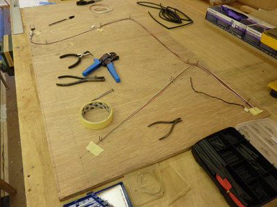 Here's the loom being assembled using 24swg wire, red and black for power and ground and white for signal and
the connectors are
JST-JWPF from RS.
Here's the loom being assembled using 24swg wire, red and black for power and ground and white for signal and
the connectors are
JST-JWPF from RS.
 Here's the loom finished and ready for installation on the bike.
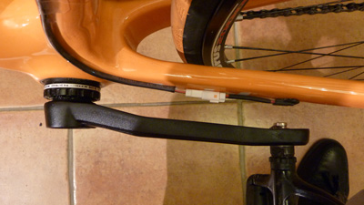 Here's the cadence sensor. I've used a
hall effect sensor from RS and a couple of 8mm diameter
neodymium magnets,
which you can just see on the end of the pedal spindle. The hall effect sensor is held in place with hot melt glue on clear tape.
Here's the cadence sensor. I've used a
hall effect sensor from RS and a couple of 8mm diameter
neodymium magnets,
which you can just see on the end of the pedal spindle. The hall effect sensor is held in place with hot melt glue on clear tape.
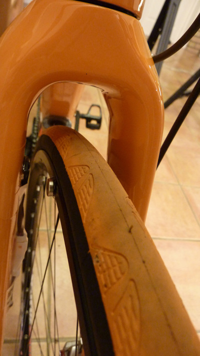 Here's the speed sensor attached to the inside of the front forks with another trigger magnet bonded onto the wheel rim.
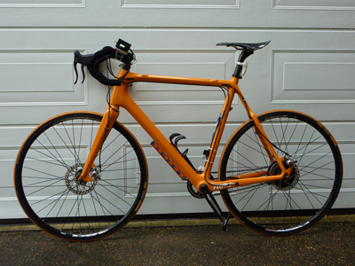 Here's the complete bike ready for it's first test run with the new logger.
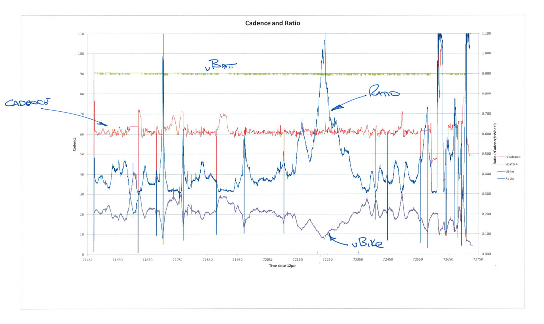
Here's some typical data taken from the logger showing a cadence target ≈ 62rpm (red) with speed (purple) and ratio (blue) which in this case is simply cadence divided by wheel speed.
The green trace is battery voltage and noise on this signal indicates shift activity in the Nuvinci hub. When the Nuvinci runs out of authority,
because it is in the highest or lowest gear ratio, the cadence changes from the demanded value and there is no shift activity influence seen on the battery voltage.
This can be seen in a few cases on this trace when going downhill as I have geared the bike for climbing and input low torque.
Where the cadence trace appears to drop out it is because I have stopped pedaling and the time period between interrupts is large.